Routing with Tom O'Donnell

 Producing such items displayed requires the construction of Jigs and Templates

This presentation is not about purchasing Jigs, as they are not readily available, it is about making  your own, in your own workshop.

One of the first jigs produced to hold material secure was simple a piece of 12mm MDF 400mm x 300mm, to which was attached the material to be cut. There are a number of methods suitable for attaching the material to the Jig.

Illustrated is the use of shelf supports 

This simple Square Jig  is produced to rout the twelve sided clock with an alternative method of cecuring the material to be cut.

Eight 'Cams' are produced. The advantage of using cams is they can be positioned for various size material

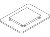
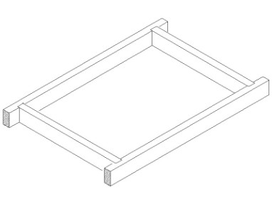
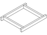
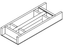
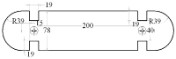
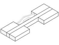
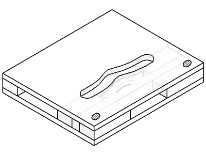
The two jigs above require some form of box construction to prevent the material from moving during the process. The two boxes I have constructed are 400mm x 300mm x 40mm,   and 300mm x 300mm x 40mm

These boxes are used extensively to produce a number of routing processes and are referred to as

'Jig Holders'

throughout this presentation

 This is the standard 400 x 300 x 40mm Jig Holder I constructed when I began to use the template guides to produce many processes that were not suitable for producing with the router in the router table.

The 300 x 300mm Jig Holder produced to rout the  12 sided clock and the Logo was a better shape as the the templates required could be reversed and flipped over to complete the processes required

When making the decision to produce any project, careful consideration should be given as to the method of construction to be used. As this is a routing project I suppose the first suggestion is to see if it can be achieved with the router in the router table or it may be necessary select other tools or machinery to complete the various stages of construction.

No matter what method is selected it has to be done with SAFETY as the main factor  

                                                  To Contact the author  email; tomann-at-iinet-dot-net-dot-au 

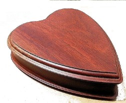
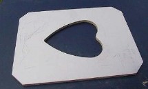
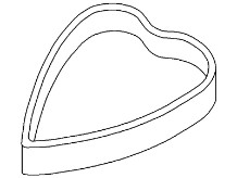
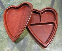
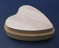
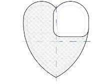
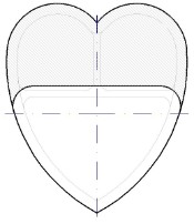
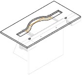
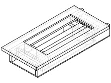
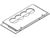
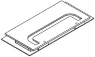
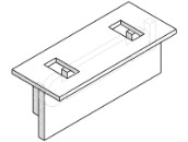
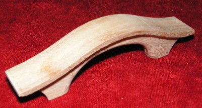
 The Heart shaped box presented below is only a sample of a number of projects that can only be constructed after a Jig Holder is produced, and with the aid of Templates, and template guides.

 In this instance only two pieces of material were used in the construction and it was necessary to construct a Jig Holder greater than 40mm deep to accommodate the thicker material required for the base of the clock..

Stage 1; Producing the Heart shaped template (400 x 300 x 12mm) and with a 40mm guide and 19mm dish cutter to rout out the inside of the box.

Note; Routing with a 10mm cutter to remove the waste material will preserve the life of the 19mm dish cutter 

To produce the external shape many would revert to the band saw or Jig saw to leave the 10mm sides and spend a great deal of time sanding the edges to achieve a satisfactory finish 

Routing the lid of the box is produced using the same method as the base construction only using thinner material.

Note; As the photograph show the base section  partitioned into three parts; this will require the preparation of two or three more templates 

Another solution is to produce a 'Plug' to fit into the base cut-out to form a 'Male' template to rout the external edge with a straight cutter.

Note; The plug should fit neatly into the base. This can be produced with the router to obtain a better finish.

Mantle Clock;

With a change in project will mean a change in how we go about setting it up in a jig and producing templates

Producing such Items as the mantle clock required some other form of holding the material secure as it was not suitable to be held in the Jig Holder described above.

Note; The clock has been produced from two pieces of material

The new Jig shows stage one for holding the material for two clocks to be routered. They are clamped to the uprights ready to shape the ends. The space in the middle is to hold the material to rout the surface of the clock.

Three template were required to complete the various processes and if you look carefully at each template you will see alternative method of holding the templates secure; each template was positioned with the aid of two dowels

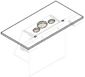
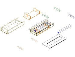
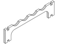
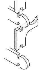
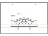
 It has been necessary to look at alternative methods of holding material secure during the routing process. This particular Jig can be inserted into the bench vice to hold it secure. Also in the first template strips are added to support the router (with the aid of router support rods) especially during the second stage routing the face of the clock. These will prevent the router from 'Tipping' into the recess when making the cut.

Note;   This particular clock was produced  by a number of V.I.Ps (Vision Impaired Persons) at the Association for the Blind in Western Australia

 Producing table or Chair legs:

Once upon a time we would not consider producing tapered legs as we did not possess a planer to make the tapers. This method is still used today as it is considered the proper method to follow. Some may consider this process can be completed with the router in the router table and I have no doubt it can. With a liitle more consideration a box like jig can be produced to support the material and the shape can be produced with the router in the plunge mode with Greater safery Awareness

As none of the above Jigs were suitable for assisting in producing the Chair leg (See Dining room chairs) other techniques had to be introduced; a jig that was suitable for shaping the legs and inserting the mortices.

 The material has to be held secure and also at an angle to enable the taper to be produced and also add the moulding to the face of the leg.(See dining room chairs). Material is positioned in the centre of the Jig holder in my 'Cradle'

Here is the Jig complete with guide to prevent the router from tipping ready to receive the various templates to assist in routing the various processes including the mortice.

Exploded view of the various parts required in the construction of the jig 

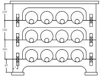
 Many ideas will spring to mind once a firm understanding on how the template guides are to be used. The 12 bottle wine rack design was taken from a routing magazine some years ago where it was demonstrated on how the small CNC router could be used to produce the parts

Design for a 12 Bottle wine rack.

A new Jig system was  introduced to secure the material in position during the routing procedure

This is the simple Jig required to hold the material secure with the aid of two screws 

Producing the number of rails to hold the bottles in position required the construction of two templates.

Note; The dowel method was used to position the templates 

 The cross rails were produced from the off-cuts when routing the rails; it was necessary to produce a jig to hold the material secure during the process

Producing the joints to connect all the sections together could be produced with tenon saw and chisel. This was a project for the blind therefore an alternative method was introduced where the router could be used 

Selecting a different approach to solving the problems with greater Safety Awareness, members of the class were able to achieve more interesting projects

Each one of the projects I have submitted have been completed with the router used mainly in the plunge mode. I am convinced that a greater number of projects can be achieved when the router is used in this mode, not to forget the greater safety awareness that is achieved also. Many of the processes I have used to produce the projects are not capable of producing on the router table (IMHO)

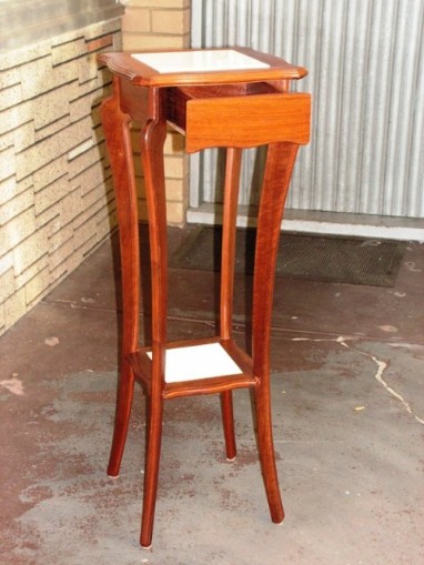
To illustrate the advantages of using the Template Guides and constructing Jigs and Templates consider the Pedestal project listed below


Start of a list of the various parts and method of producing each part 

(1) Producing the four legs; we have a choice as to which method to be used. Making a 'Male' Template  and trimming to size with a Cutter bearing top or bottom

 Router Table

Plunge mode

 (2) Producing the four rails of  similar shape as shown in the photograph

Router Table

Plunge mode 

(3) Constructing the Top surface from four pieces of material and producing a rebate for  a Tile  

Router Table 

 Plunge mode

(4) Constructing the lower shelf similar to the top surface only with a smaller tile 

Router Table 

 Plunge mode

 There is no doubt a 'Band Saw ' could play a major roll in shaping the legs and rails and a Drop Saw / Mitre Saw, would be the tool to use to cut the mitres required. When this was presented to the class at the Association for the blind these machines had to be discarded due to safety reasons, therefore a number of jigs and template were required for the clients to produce this pedestal with Safety 

Also to be taken into consideration, was the method of producing the necessary joints required for the construction

This project has been highlighted to illustrate that it can be achieved with the router, especially if we do not have the 'Band Saw' or 'Drop / Mitre saw' in our work shop. Not only is use of the template guides considered safe for the blind clients, it will also introduce New routing Techniques to allow the average wood worker to use the router with more confidence. The router table has not been used to complete this project. Note; To add the mouldings to the edges of the various parts I had to introduce an alternative method which added greater safety awareness. (Overhead Routing)

There is a great deal more that can be written on how this project was completed, this is one of my projects that has been produced but I still require to write the procedures describing the method I have used 

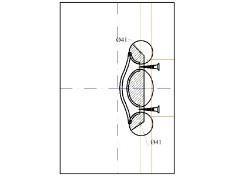
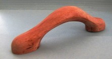
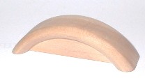
 Cabinet Handles (Wooden)

Cabinet handles may not be available in the same material as the cabinet you are in the process of construction so why not make your own simply by constructing a simple jig and a couple of templates 

 None of the previous jigs and template would be suitable to produce this next project. The Jig set-up is not like any of the others I have used in the past so there is a need to rethink the method of achieving the design of the handle shown in the Photograph opposite.

The jig is made up from the same thickness material as the handle as seen in the drawing and is held secure with two screws 

The template illustrated is suitable for routing the external shape of the handle with the aid of a template guide and a straight cutter 

Template two is required to be produced as a pair to rout from both sides the face of the handle ; it will be 'flipped' over to rout the other side

 With a third template the final shape of the handle can be achieved with safety with a template guide and a straight cutter

The rounding over can achieved when the Templates above are positioned; again 'flipping' the jig over to complete the other side

 Other handle designs are available for routing with safety

New jig and templates will be required to rout this handle 

When even smaller handles are required new templates will be required 

Make a Free Website with Yola.